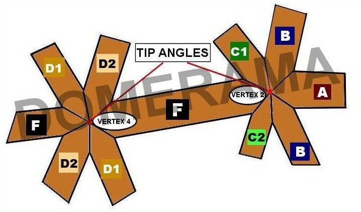
4V timber dome construction
Building a geodesic dome from timber is often preferred when the structure needs to be more permanent, such as for a greenhouse. Another advantage is the ease with which you can cover a timber dome: whether you cover the dome with plywood, polycarbonate panels or another material, installation is simpler than with metal used for struts.
On the other hand, metal struts can be flattened and drilled to be assembled with bolts, something you cannot do with timber; you have two options; use hubs to hold the hubs together at each vertex, or cut each strut tip at the correct angle.
Hubs can sometimes be expensive, especially since you need a large number of them. You can save money by making them yourself but the cuts are almost always “compound cuts”. If you ever used or watched someone using a mitre saw, you noticed the angle of the cut AND the tilt of the blade are both adjustable. This is what we call a compound cut.
Before you embark on a hubless 4v geodesic timber dome
It’s very simple: unless you have large amounts of time, skills and patience, do not attempt this project. It will truly test your limits as you wil not have many to fall back on in case problems arise. Geodesic dome hub connectors is the smartest way to go.
4v chord factors
Here below are the chord factors for a 4v geodesic dome. You can calculate your strut lengths using these numbers or use the calculators on this site. These chord factors can be used for various 4v truncations. This means you can use these chord factors for a 6/12 dome (half of a sphere) a 5/12 or 7/12 truncation (less or more than half of a sphere) or any other truncation of a 4v.
STRUT A: 0.253185
STRUT B: 0.295242
STRUT C: 0.294531
STRUT D: 0.312869
STRUT E: 0.32492
STRUT F: 0.298588
Types of triangles
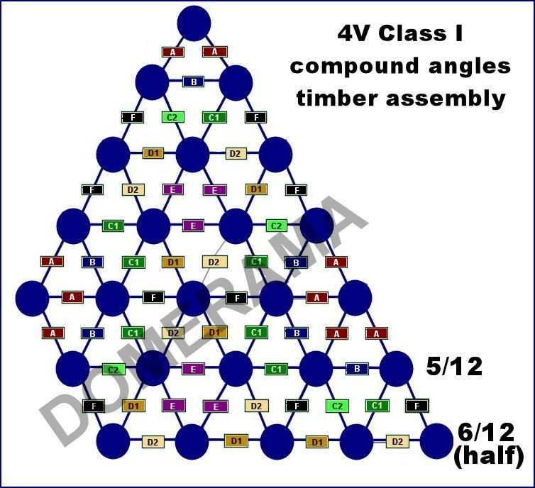
There are 6 types of triangles:
BAA
BC2C1
FC1D2
FD1C2
ED1D2
EEE
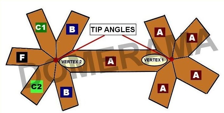
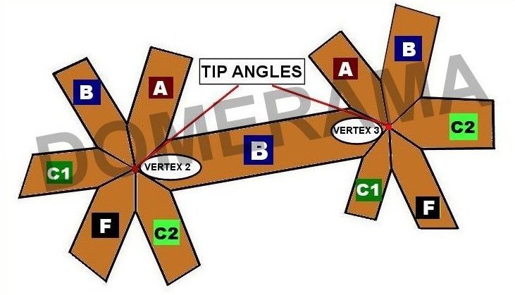
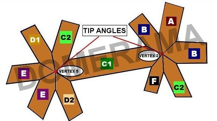
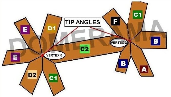
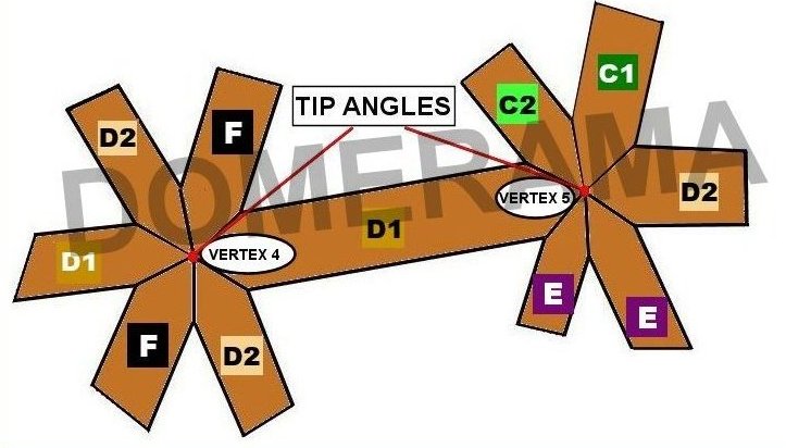
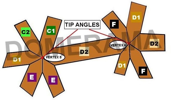
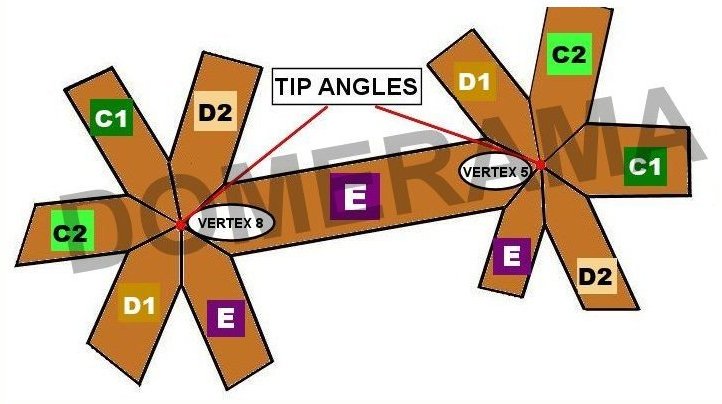
Note that the tip angles for any vertex will not add up to 360 degrees. Also, the tip angles will not equal the sum of the face angles of triangles which converge at that same vertex.
Anatomy of a double-bevel compound angle in a geodesic dome
Here are two diagrams to help explain the terminology used on this page
Below SA1 + SA2 = partial “tip angle” + partial “tip angle” = full “tip angle”.
MS = arcos (tan BS x tan SA)
BS = arctan (cos MS / tan SA)
SA = arctan (cos MS / tan BS)
For example, if MS = 20 degrees and BS1 = 40 degrees, then SA1 = 48.24 degrees.
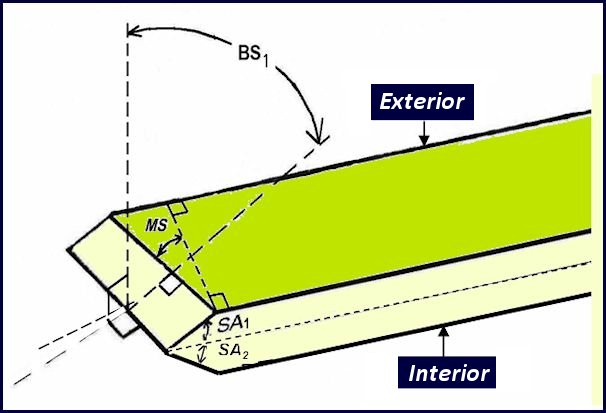
AA = axial angle (i.e., 90 – MS)
MS = mitre setting angle or saw’s swing angle
BS = bevel setting angle or saw blade’s tilt angle
SA = supplementary angle or strut-edge angle (slightly larger than half the dome triangle face angle)
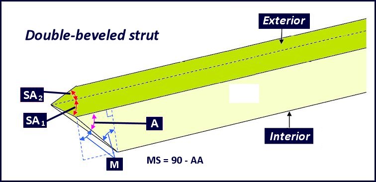
How compound cuts are made
 |
 |
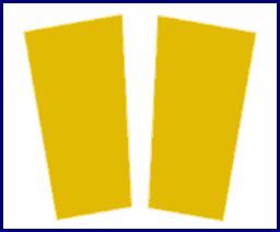 |
| Two cuts are made at the tip of each strut. | The side view shows another angle to cut. This one is the same as what you get when using a geodesic calculator | Making a geodesic dome from individual triangles requires a cut or bevel along the length of each strut side to fit with adjoining ones. |
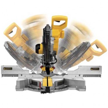
A mitre saw can change blade tilt and cut angle
A note regarding cutting compound angles
This is not to be seen as an easy project. You need patience, very good equipment and very good knowledge of what you are doing. Compound angles are very difficult for the novice. This type of work is best left to experienced woodworkers.
Another note to make about equipment: not all mitre or radial arm saws have the ability to cut at the angle required and the adequate depth. The specifications for a saw are usually easy to find in its description. For example, a saw may cut at the proper angle on a 2″ X 4″ stud but may not work on a 2″ X 6″ because you may need to cut more than 6 inches deep.
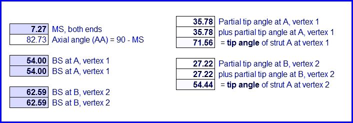
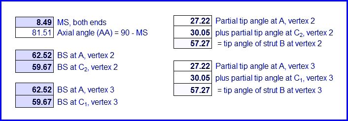
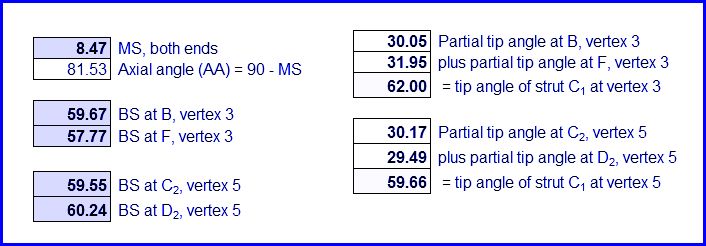
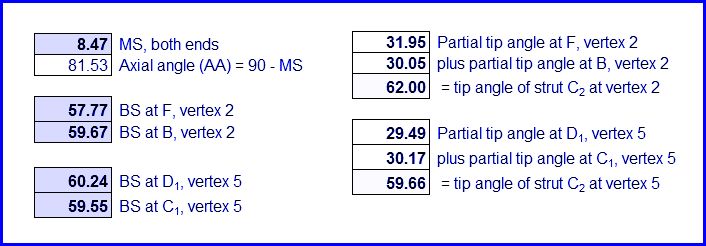
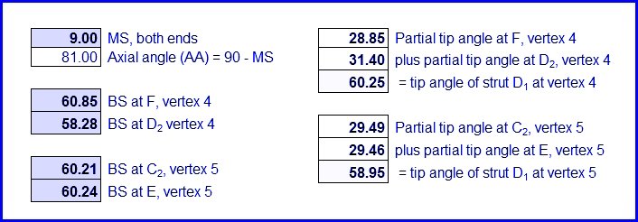
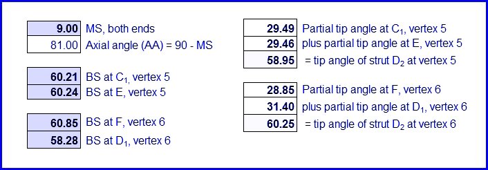
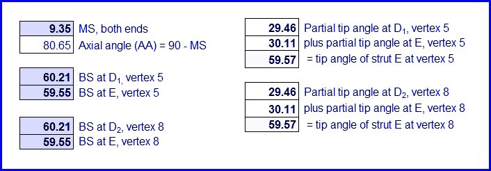
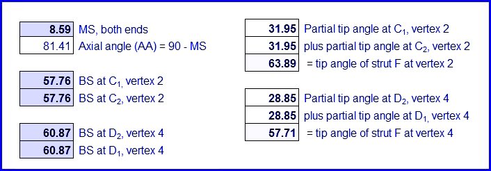
The images below display information regarding each strut.
